Single Pair Ethernet (SPE): SPE Cabling & Connector Guide
Author: Jonas Gesch
Job Title: Field Application Engineer
This document serves as a guide on the different cable and connector types used for the physical layer of Single Pair Ethernet (SPE). The standardization landscape for SPE has historically been rather inhomogeneous with several competing connector standards available and the promise of being able to reuse existing legacy cabling. As a result, the question of which cables and connectors can be used for SPE links has become very complex. This guide provides an overview of the available standards as well as non-standard connectors and discusses the possibility of retrofit installations through the reuse of existing cables.
Single Pair Ethernet (SPE) represents a significant shift in communication technology, specifically designed to bridge the "Ethernet gap" that exists between high-level management networks and the field level. Historically, while enterprise and control levels have utilized standard Ethernet, the field level – where sensors and actuators reside – has been dominated by various legacy fieldbus protocols (such as BACnet, Modbus, and Profibus). These protocols often create isolated data silos, trapping valuable information behind protocol gateways, significantly inhibiting the digitalization and automation capabilities of those systems.
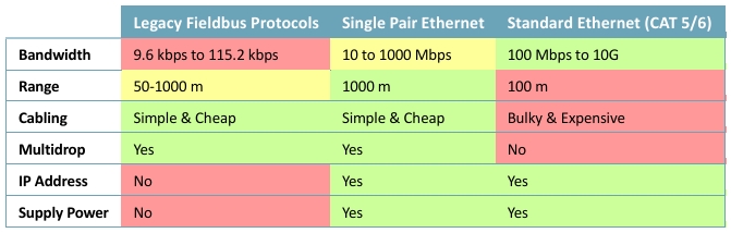
Single Pair Ethernet provided a solution to this issue by combining most important advantages of both fieldbus protocols and Standard Ethernet as can be seen in Table 1. It has evolved into a key technology for industrial and building automation, offering both the physical simplicity and long-reach capabilities of legacy fieldbus and the high speed, IP-addressability, and power delivery (PoDL/SPoE) of modern Ethernet. This unified approach allows for a 10x extended range compared to standard Ethernet and a 10x to 100x increase in data bandwidth compared to many fieldbus protocols, enabling seamless data flow from the sensor to the cloud without the need for expensive translation gateways.
Table 1: Comparison of SPE with fieldbus protocols and standard Ethernet
Despite its clear advantages, several challenges currently complicate the selection and deployment of SPE infrastructure:
One of the most significant hurdles has been the lack of a single, universally adopted mating face for connectors. For years, the industry was divided between different standardized designs, which led to uncertainty and a reluctance among manufacturers to fully commit to SPE. While progress is being to harmonize IP20, M8, and M12 interfaces made through the newly published IEC 63171-7 standard navigating these options remains complex for system designers.
While the potential for reusing existing serial cabling is a major selling point for retrofitting (especially in building automation), there has been a lack of specific technical guidelines for these markets. Determining the maximum transmission length and signal integrity over older, non-standardized cables requires careful technical evaluation.
Industrial automation markets are traditionally conservative when introducing new communication layers. This cautious approach, combined with the technical nuances of power distribution (PoDL vs. SPoE) and environment-specific requirements, adds a layer of complexity to the initial design phase.
The simplified cabling of SPE with only a single twisted wire pair is one of its most attractive advantages over the two- or four-pair CAT5/6 Ethernet cables. This design makes the cable more flexible and easier to install while also reducing cabling weight, cable diameter and the required copper by up to 50%[1],[2], which in turn decreases the cable costs and carbon footprint.
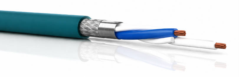
Figure 1: Single twisted-pair cable used for SPE
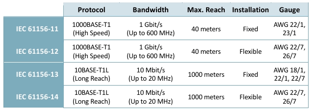
The IEC 61156 series shown in Table 2 serves as the primary technical foundation for the design and manufacturing of symmetrical communication cables, categorized by installation type and performance requirements. Part 11 to Part 14 of the standard specifically define standardization for single pair cables, officially supported by the SPE Industrial Partner Network and SPE System Alliance.
Table 2: Comparison of IEC 61156 SPE cable standards
Draka Comteq, a member of the SPE System Alliance, performed extensive tests on the backwards compatibility of running field bus protocols over SPE cables, claiming full compatibility with RS485 and BACnet as well as restricted compatibility with Foundation Fieldbus, Profibus PA and CAN bus.[3]
A major selling point for SPE, particularly the 10BASE-T1L standard, is its ability to operate over legacy twisted-pair cabling originally installed for serial protocols like RS-485, CANBUS, or BACnet. Retrofitting existing cabling can drastically reduce installation costs by avoiding the need to pull new wires.
The test results in Table 3 show the maximum cable distance that different legacy cable types were able to reach while transmitting data using the 10BASE-T1L SPE protocol with no packet loss. It is worth mentioning that these results should only be taken as reference since real-world performance will vary depending on cable condition, patch connections, connector types, and the connected end-devices.
Table 3: Maximum distance achieved when testing SPE on legacy cables.
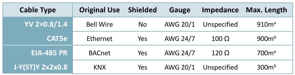
[a] According to cable test results by Phoenix Contact [4]
[b] According to cable test results by Volktek
When identifying cables suitable for retrofitting with SPE, twisted pair cables with a gauge of AWG 24 to AWG 18 and an impedance near 100 Ω are potential candidates. But as the results in Table 3 demonstrate, there is no straightforward way to assess how SPE performs on a legacy cable simply based on its specifications. For older cables which were not designed to follow comprehensive modern standards with many more controlled parameters, the feasibility of retrofitting often depends on the manufacturing of the cable. Therefore, careful evaluation of cable characteristics and conditions is necessary before reusing legacy communication cables for SPE.
To evaluate existing legacy cabling for potential reuse with SPE, several factors must be taken into consideration to ensure signal integrity:
Expected Reach: While the standard specifies 1 km, legacy cables may achieve shorter distances depending on wire gauge and cable condition.
Cable Types: High-quality shielded serial communication cables are most suitable for reuse, as they offer better protection against electromagnetic interference.
Open Branch Lines: In legacy bus topologies, it was common to have "stubs" or branch lines. For SPE, these must be terminated or removed, as open branch lines create significant signal reflections that can disrupt communication.
Return Loss: Impedance mismatches between legacy cables and modern SPE transceivers can cause signal reflections. Return loss should be carefully measured, as faults or poor-quality splices in existing runs can cause performance to deteriorate.
Insertion Loss: For long-distance retrofits, signal attenuation (insertion loss) is the primary limiting factor. Engineers must verify that the cable's insertion loss across the 20 MHz frequency band remains within the limits of the 10BASE-T1L.
The landscape of SPE connectors has long been contested with multiple standards covering overlapping application areas, some of which have struggled to adopt or have since been withdrawn. Additionally, non-standard connectors are also commonly used, mostly in form of terminal block connectors for simplified retrofitting.
While IEC 61156 defines the single pair cables used for SPE, the connector standards are defined in the IEC 63171 series. It is currently comprised of 7 connector types, which are listed in Table 4. Recently, two primary mating faces lead the market: the IEC 63171-2 compact IP20 connector, which is being pushed by the SPE System Alliance, and the IEC 63171-6 T1 Industrial connector, which is supported by the SPE Industrial Partner Network.
Table 4: Comparison of SPE connector standards
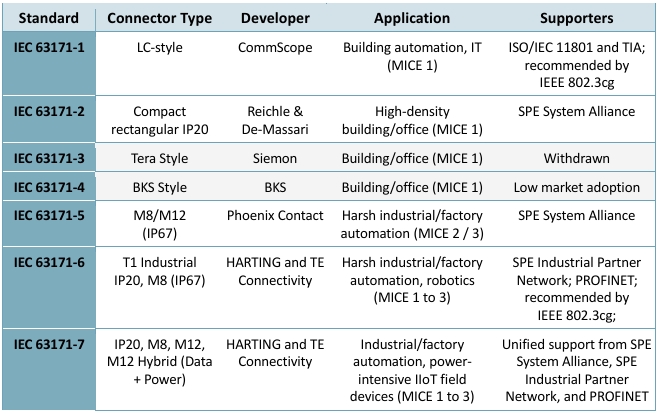
The IEC 63171-2 connector on the left of Figure 2 is often favored for building automation and office environments due to its compact form factor, which allows for doubling the port density compared to standard RJ45. The IEC 63171-6 connector also offers IP20 options but mostly focuses on M8 connectors for harsher industrial environments and factory automation, where it competes with IEC 63171-5, an IP67-rated M8/M12 connector based on the mating face of the Type 2 connector.
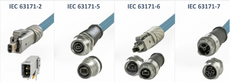
Figure 2: Overview of actively used connectors standards
More recently, both the SPE System Alliance and the SPE Industrial Partner Network have declared their support for IEC 63171-7. The standard utilizes the full range of IP20, M8 and M12 connectors and introduces an M12 Hybrid interface to combine the two-wire SPE data link with additional power pins offering power profiles such as 2x 800W at 60VDC or 9kW at 600VDC depending on the pin configurationv. This far exceeds the capabilities of PoDL and SPoE, effectively extending SPE application from low-power sensors to high-demand actuators like heavy-duty motors or complex HVAC dampers.
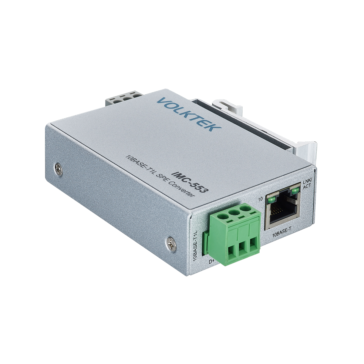
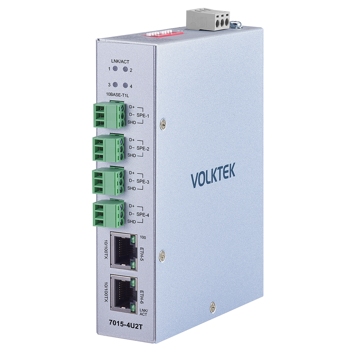
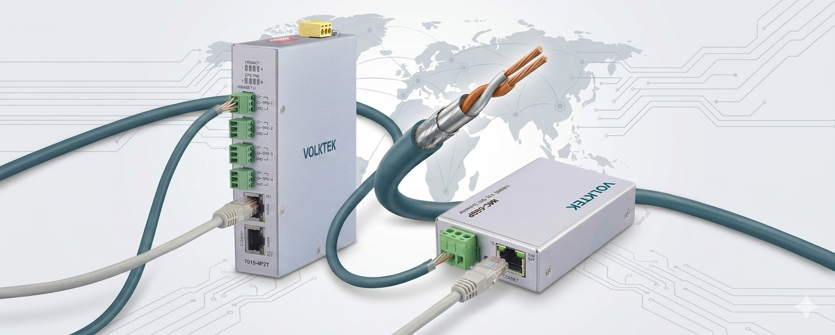
Other than the standardized connectors, there are also non-standardized versions being used. Most notably, terminal block connectors as seen in Figure 3 are frequently used for their simplicity and flexibility. They provide an easy to install screw-type interface with two pins for the twisted wire pair and one pin for the cable shielding. This makes them uniquely suited to retrofit existing networks where flexibility and easy installation are essential, especially in building automation.
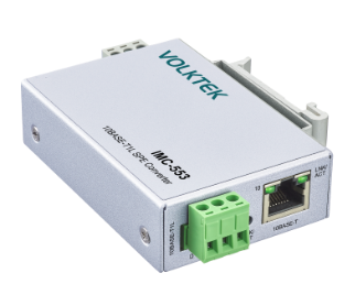
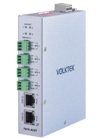
Figure 3: Volktek SPE devices with terminal block connectors for simplified retrofit installation.
Compared to IEC 63171-2 or IEC 63171-7 connectors (which are limited to thinner 26–22 AWG wiring), 3-pin terminal block connectors can accommodate a much wider range of wire gauges (28–12 AWG). Crucially, this allows customers to easily terminate thicker 20 AWG or 18 AWG conductors, which are the industry "sweet spot" required to achieve the full 1,000-meter 10BASE-T1L distance without signal degradation.
Since there is currently only a limited number of SPE end-devices available, using a terminal block connector on the SPE switch also effectively increases the pool of end-devices to draw from. Instead of limiting the options to just one connector type, any device regardless of the used connector can be compatible by simply screwing the open wires into the terminal block on one end of the cable to then connect it to the SPE switch. This makes it well suited for adopting SPE right now without being locked into a connector ecosystem that might become obsolete when IEC 63171-7 gains traction.
One of the major selling points of SPE is the ability to run over reused existing legacy communication cables like YV 2×0.8/1.4, J-Y(ST)Y 2x2x0.8 or RS-485. While this is definitely possible, retrofitting is not without challenges. The achievable distance without signal degradation depends on the cable characteristics, so careful evaluation is required.
When it comes to the connector standards, IEC 63171-2 and IEC 63171-6 are currently most widely in use. However, the recent emergence of the IEC 63171-7 standard promises to unite the previously divided SPE connector ecosystems with both the SPE System Alliance and the SPE Industrial Partner Network pushing for its adoption. Meanwhile, terminal block connectors offer a simple and cost-effective way of building up your SPE network without being locked into a connector type. Additionally, their flexibility provides a unique advantage for retrofitting legacy communication networks with SPE devices, especially in the building automation industry.
A: Retrofitting 10BASE-T1L SPE on existing twisted pair cables is possible but depends on the characteristics and condition of the cable as well as the transmission distance.
A: When evaluating legacy cables for reuse, factors that need to be considered include wire gauge, impedance, shielding, insertion loss, return loss and unterminated branch lines.
A: Currently, most devices use either IEC 63171-2, IEC 63171-6 or terminal block connectors with adoption of IEC 63171-7 expected to increase.
A: Terminal block connectors offer flexibility and easy installation, significantly simplifying retrofit installation with existing legacy cabling.
A: It is the first standard that the two major SPE partner networks jointly support, which promises to finally unify the SPE connector landscape under one standard. It also introduces an M12 Hybrid connector, capable of powering high-demand equipment.
Volktek Corporation is a Taiwan-based manufacturer specializing in industrial Ethernet networking solutions with more than three decades of experience in supporting industrial automation, building management system, maritime, transportation, energy, and critical infrastructure applications. Volktek focuses on delivering reliable, secure, and easy-to-deploy networking products that operate consistently in harsh industrial environments. With in-house design, manufacturing, and quality control, Volktek supports customers worldwide through the full product lifecycle – from system design and deployment to long-term operation and technical support. Our portfolio emphasizes robustness, long product availability, and practical security features to help customers build resilient and future-ready OT networks.
[1]Helukabel, "Single Pair Ethernet", HELUKABEL White Paper, August 2020.